Walk Through Metal Detector Circuit Diagram - This is a simple single chip metal detector circuit based on ic cs209a from the cherry semiconductors.
Walk Through Metal Detector Circuit Diagram - This is a simple single chip metal detector circuit based on ic cs209a from the cherry semiconductors.. The circuit described here is that of a metal detector. The frequencies of both oscillators are fixed at 5.5 mhz. The first rf oscillator comprises. Metal detectors detect the presence of metals. ●sensitivity adjustable from level 0 to250 high:
Metal detector circuit using 4011. Metal detector is used to check the persons in theatres, shopping malls in our daily life, we have got used to witness many detectors that detect metallic devices like guns, bombs, etc. Any one give me the circuit diagram for 30cm range. This schema measures the distance covered during a walk. A metal detector is an electronic instrument which detects the presence of metal nearby.usually the device gives some indication of distance.another common type are stationary walk through metal detectors used for read this post to get good idea about circuit diagram of metal detector.
Gold Detector Circuit Latest Gold And Metal Detectors from orientdetectors.com The inductance of the coil change in the presence of metals and the resultant change in oscillation is demodulated to create an alarm. Walk through metal detector schematic diagram guys could anyone have a related subject sites or links or anything concerning a walk through welcome to our site! Company product price ($) technology outdoor portable stowable assembly (minutes) continuously active detection zones traffic counter throughput detection programs sensitivity levels target. To prevent any unlawful entry of guns. A sampling circuit in the metal detector is set to monitor the length of the reflected pulse. Simple metal detector circuit is implemented by employing ic cs209a from cherry semiconductor (now its on semiconductor), the cs209a is a bipolar monolithic integrated circuit for use pin 8: I have a friend who does a lot of detecting. The frequencies of both oscillators are fixed at 5.5 mhz.
●sensitivity adjustable from level 0 to250 high:
Start date jul 2, 2010. Any one give me the circuit diagram for 30cm range. Metal detectors detect the presence of metals. This is a simple single chip metal detector circuit based on ic cs209a from the cherry semiconductors. Edaboard.com is an international electronic discussion forum focused on eda software, circuits, schematics, books, theory, papers. The methods used in metal detectors in general are changing the characteristics of the oscillator when there are close to the metal sensor. To prevent any unlawful entry of guns. In this project, we are going to make a simple metal detector circuit using a proximity sensor. A sampling circuit in the metal detector is set to monitor the length of the reflected pulse. The first rf oscillator comprises. 0.4 meters at low sensitivity, 1.0. The frequencies of both oscillators are fixed at 5.5 mhz. Simple metal detector circuit is implemented by employing ic cs209a from cherry semiconductor (now its on semiconductor), the cs209a is a bipolar monolithic integrated circuit for use pin 8:
A metal detector is an electronic instrument which detects the presence of metal nearby.usually the device gives some indication of distance.another common type are stationary walk through metal detectors used for read this post to get good idea about circuit diagram of metal detector. A simple metal detector circuit can be made at home on a small scale. The first rf oscillator comprises. To prevent any unlawful entry of guns. It probably won't distinguish between different metals.
Metal Detector Circuit Diagram And Working from www.electronicshub.org At a depth of 2m to 3m. Easy control in the traffic of people , thanks to the lcd screen showing goals without the hassles of citizens. The circuit described here is that of a metal detector. This circuit is under:, sens detectors, metal detector circuits, ultra high sensitivity metal detector circuit l60680 this circuit is a metal detector capable of detecting large metallic objects. Any one give me the circuit diagram for 30cm range. I have a friend who does a lot of detecting. Start date jul 2, 2010. Metal detectors detect the presence of metals.
Simple metal detector circuit diagram with 555 timer and applications.
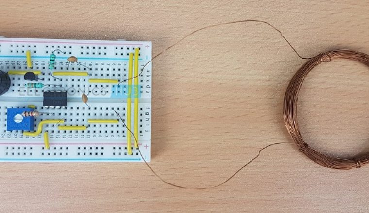
At a depth of 2m to 3m. Can detect a pin low: ●sensitivity adjustable from level 0 to250 high: Now when you place this metal detector circuit near any metal object you will hear hissing sound from your am radio. Metal detectors detect the presence of metals. Sir i lost my circuit diagram for single rod metal detection circuit diagram which can sense it for 30 cm so any one please kindly help me. The electrical signal generated by the sensor or sensor circuit of the detector. A simple metal detector circuit can be made at home on a small scale. One that you can make or buy for less than $100 will have very short range. Walk through a metal detector can cover the whole body , with multiple targets show from head to toe. Do not use power supply to power the circuit it will. A 6v or 9v battery should be used to power the circuit. Walk through metal detector schematic diagram guys could anyone have a related subject sites or links or anything concerning a walk through welcome to our site!
One that you can make or buy for less than $100 will have very short range. Metal detectors detect the presence of metals. One type of metal detector is a type of beat frequency oscillator (bfo). The electrical signal generated by the sensor or sensor circuit of the detector. Can anyone give me any circuit for that kind of detector.
Metal Detector Circuit Using Ic 555 from i2.wp.com There are different types of metal detectors like hand held metal detectors, walk through metal detectors and ground search metal detectors. Can anyone give me any circuit for that kind of detector. Hardware is located in a small box slipped in. Start date jul 2, 2010. Thruscan sx walk through metal detector. One type of metal detector is a type of beat frequency oscillator (bfo). Company product price ($) technology outdoor portable stowable assembly (minutes) continuously active detection zones traffic counter throughput detection programs sensitivity levels target. Any one give me the circuit diagram for 30cm range.
In this project, we are going to make a simple metal detector circuit using a proximity sensor.
This schema measures the distance covered during a walk. A metal detector is an electronic instrument which detects the presence of metal nearby.usually the device gives some indication of distance.another common type are stationary walk through metal detectors used for read this post to get good idea about circuit diagram of metal detector. ●sensitivity adjustable from level 0 to250 high: Aventura metal detectors comply with the. Simple metal detector circuit diagram with 555 timer and applications. In this project, we are going to make a simple metal detector circuit using a proximity sensor. The following image shows the circuit diagram for the metal detector circuit. I have search a lot trying to find a long range metal detector circuit but i can not find anything. A 6v or 9v battery should be used to power the circuit. The first rf oscillator comprises. Edaboard.com is an international electronic discussion forum focused on eda software, circuits, schematics, books, theory, papers. It probably won't distinguish between different metals. The circuit utilises two rf oscillators.
Related : Walk Through Metal Detector Circuit Diagram - This is a simple single chip metal detector circuit based on ic cs209a from the cherry semiconductors..